Archivo:Inductively coupled crystal radio circuit.svg
Ir a la navegación
Ir a la búsqueda

Tamaño de esta previsualización PNG del archivo SVG: 722 × 435 píxeles. Otras resoluciones: 320 × 193 píxeles | 640 × 386 píxeles | 1024 × 617 píxeles | 1280 × 771 píxeles | 2560 × 1542 píxeles.
Archivo original (archivo SVG, nominalmente 722 × 435 píxeles, tamaño de archivo: 36 kB)
Resumen
| Descripción |
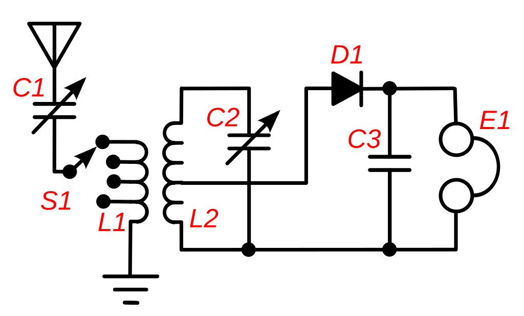
English: A circuit of an inductively-coupled crystal radio receiver with impedance matching. This type of circuit, called a "two circuit" or "loose coupler" receiver, was used in most sophisticated crystal receivers from the wireless telegraphy era which ended in the 1920s, until today. Instead of a single tuning coil, it has an antenna coupling transformer (L1,L2) which improves the poor selectivity found in most crystal receivers. Each coil functions as a tuned circuit; the primary L1 resonating with the capacitance of the antenna and the primary tuning capacitor C1 and the secondary resonating with the secondary tuning capacitor C2. The two tuned circuits interact, resulting in a much narrower bandwidth (higher Q) than a single tuned circuit when the two coils are loosely coupled. However looser coupling also reduces the amount of signal getting through the transformer. So the coupling was made adjustable. When interference was encountered the coils were separated to sharpen the bandwidth and reject the interference. Adjustable antenna matching is provided by attaching the antenna to a tap on L1 which can be selected by switch S1. This maximizes the power transferred from the antenna to the receiver by matching the low impedance of the antenna-ground circuit (around 10-200 ohms) to the higher impedance of the tuned circuits, using L1 - L2 as an impedance matching transformer. The turns ratio was adjusted with switch S1 until the station sounded loudest in the earphone E1. To improve power transfer the crystal detector D1 is also impedance matched to the tuned circuit by attaching it to a tap on L2. This also improves the Q of the tuned circuit, increasing the selectivity, because it reduces the resistive "loading" of the diode-earphone circuit on the tuned circuit. Capacitor C3 bypasses the pulses of carrier to ground, leaving only the audio signal to pass through the headphones. |
| Fecha | |
| Fuente | Trabajo propio |
| Autor | Chetvorno |
| SVG desarrollo |
Licencia
I, Chetvorno, the author of this work, release it into the public domain for any use whatever.
| Yo, el titular de los derechos de autor de esta obra, lo libero al dominio público. Esto aplica en todo el mundo. En algunos países esto puede no ser legalmente factible; si ello ocurriese: Concedo a cualquier persona el derecho de usar este trabajo para cualquier propósito, sin ningún tipo de condición al menos que éstas sean requeridas por la ley. |
Historial del archivo
Haz clic sobre una fecha y hora para ver el archivo tal como apareció en ese momento.
| Fecha y hora | Miniatura | Dimensiones | Usuario | Comentario | |
|---|---|---|---|---|---|
| actual | 05:15 9 may 2017 | | 722 × 435 (36 kB) | wikimediacommons>Chetvorno | Replaced invalid version with "plain SVG" version that passes validation |
Usos del archivo
La siguiente página usa este archivo: