Archivo:Optical flat interference.svg
Ir a la navegación
Ir a la búsqueda

Tamaño de esta previsualización PNG del archivo SVG: 715 × 599 píxeles. Otras resoluciones: 286 × 240 píxeles | 573 × 480 píxeles | 916 × 768 píxeles | 1221 × 1024 píxeles | 2443 × 2048 píxeles | 1417 × 1188 píxeles.
Archivo original (archivo SVG, nominalmente 1417 × 1188 píxeles, tamaño de archivo: 48 kB)
Resumen
| Descripción |
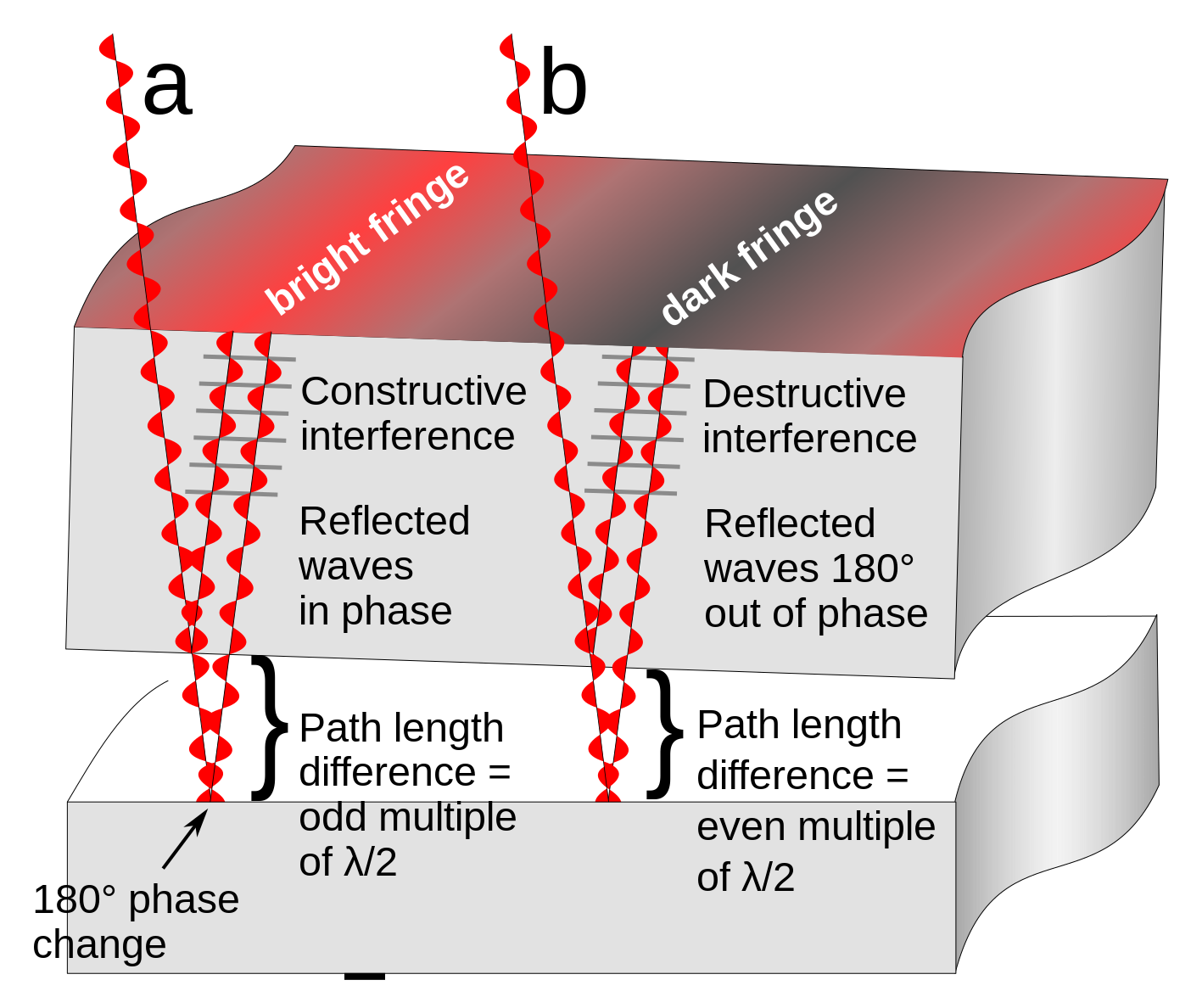
English: Diagram showing how interference fringes are created by an optical flat. The upper object is a section of a glass optical flat resting on another flat reflective surface. Light rays (red) from a monochromatic light source pass through the flat and reflect from both the bottom surface of the glass and the surface it is resting on. Since there is a tiny gap between the two surfaces, the ray reflecting off the bottom surface travels a greater distance than the top ray. It also experiences a 180° phase change at the reflection from the bottom plate (the reflection from the top plate causes no phase change). The parallel rays superpose. At locations (a) where the extra distance travelled by the 2nd ray (twice the width of the gap) is equal to an even multiple of a half-wavelength (λ/2) of the light the two reflected waves will be in phase and will add, reinforcing each other, resulting in a bright reflected ray. This is called constructive interference. At other locations (b) the path difference between the rays is equal to an odd multiple of λ/2, so the reflected waves are 180° out of phase. They subtract, canceling each other out, resulting in little or no reflected light. This is called destructive interference.
When the two surfaces are not parallel, as in the diagram, this results in a pattern of alternating bright and dark bands visible on the surface, called interference fringes. Two adjacent interference fringes represent a difference in height of the surface of one-half wavelength of the light used, so interference patterns can be used to measure the flatness of surfaces to millionths of an inch. In this diagram the width of the gap and the wavelength of the light waves is greatly exaggerated; light has wavelengths around 10-7 meter.Русский: Интерференция в тонком воздушном клине |
| Fecha | |
| Fuente | Trabajo propio |
| Autor | Chetvorno |
| Otras versiones |
|
| SVG desarrollo |


Licencia
Yo, el titular de los derechos de autor de esta obra, la publico en los términos de la siguiente licencia:
| Este archivo está disponible bajo la licencia Dedicación de Dominio Público CC0 1.0 Dedicación a Dominio Público Universal de Creative Commons. | |
| La persona que ha asociado una obra a este documento lo dedica al dominio público mediante la cesión mundial de sus derechos bajo la ley de derechos de autor y todos los derechos legales adyacentes propios de dicha, en el ámbito permitido por ley. Puedes copiar, modificar, distribuir y reproducir el trabajo, incluso con objetivos comerciales, sin pedir aprobación del autor.
|
Historial del archivo
Haz clic sobre una fecha y hora para ver el archivo tal como apareció en ese momento.
| Fecha y hora | Miniatura | Dimensiones | Usuario | Comentario | |
|---|---|---|---|---|---|
| actual | 16:45 16 ene 2022 | | 1417 × 1188 (48 kB) | wikimediacommons>Aiden1123 | Reverted to version as of 03:54, 9 May 2017 (UTC) |
Usos del archivo
La siguiente página usa este archivo: